Control
PLC scan cycle and data sampling error
Before reading a PLC tag for AI, know where in the scan cycle the value was produced and which timestamp describes it.
 KutupASP Dijital
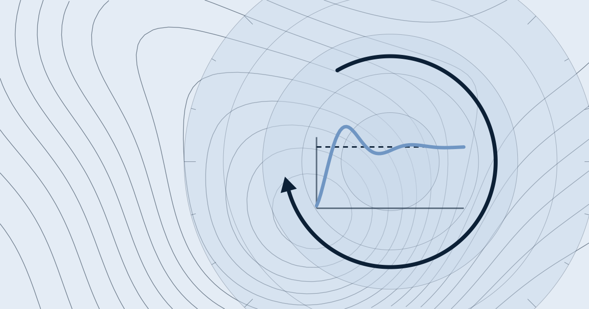
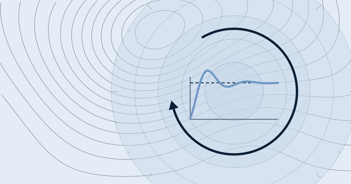
A PID loop often oscillates when the gain is too high, the integral is faster than the process lag, dead time is large, or valve stiction is present. Examine the oscillation period, controller output and measurement together. Lowering the gain is usually the first safe step.
Oscillation starts when the loop cannot balance its gain against its delay. With high gain, a small error produces a large correction, and the correction overshoots. If the integral time (Ti) is much shorter than the process lag, the I term reacts to information that arrives late, and the system hunts. Dead time, the delay between a change in output and the change in measurement, adds phase lag.
Valve stiction and backlash make the valve move in jumps. The loop may then settle into a sustained oscillation known as a limit cycle. Output saturation adds to the problem through integral windup, and noise in the measurement is amplified by the derivative term.
On a temperature loop, only P is active and the gain is increased. At an ultimate gain Ku = 4, the output oscillates steadily at constant amplitude. The period of that oscillation is measured as Pu = 20 s (hypothetical). Using the classic Ziegler–Nichols closed-loop rules:
These are only a starting point. If the loop still oscillates, lowering Kp further or increasing Ti may be needed.
The first step is to measure the oscillation period. A short period often points to high gain or a noisy derivative; a long period suggests a slow integral or a large process delay. The period alone is not enough, so plot the controller output and the measurement on the same chart. With valve stiction, the controller output can look like a square or triangular wave. A common mistake is trying to remove the oscillation by changing tuning alone. Check the valve, positioner and sensor first.
Start with valve maintenance, reducing packing friction and checking the positioner. If needed, use a deadband or an output rate limit on the controller side. Changing tuning alone hides the symptom, and the oscillation can return until the mechanical problem is fixed.
That can happen, because process gain and delay change with the operating point. When load, flow or product changes, the same tuning can oscillate under the new conditions. In that case, consider tuning sets for each operating point, or a gain schedule, rather than one fixed setting.
Example numbers are hypothetical, not measured field results.
Before reading a PLC tag for AI, know where in the scan cycle the value was produced and which timestamp describes it.
Alarm floods are solved with an alarm philosophy first, not a model. AI works better on an orderly alarm list.